
CAN Hub — F9P and H-Flow on one bus
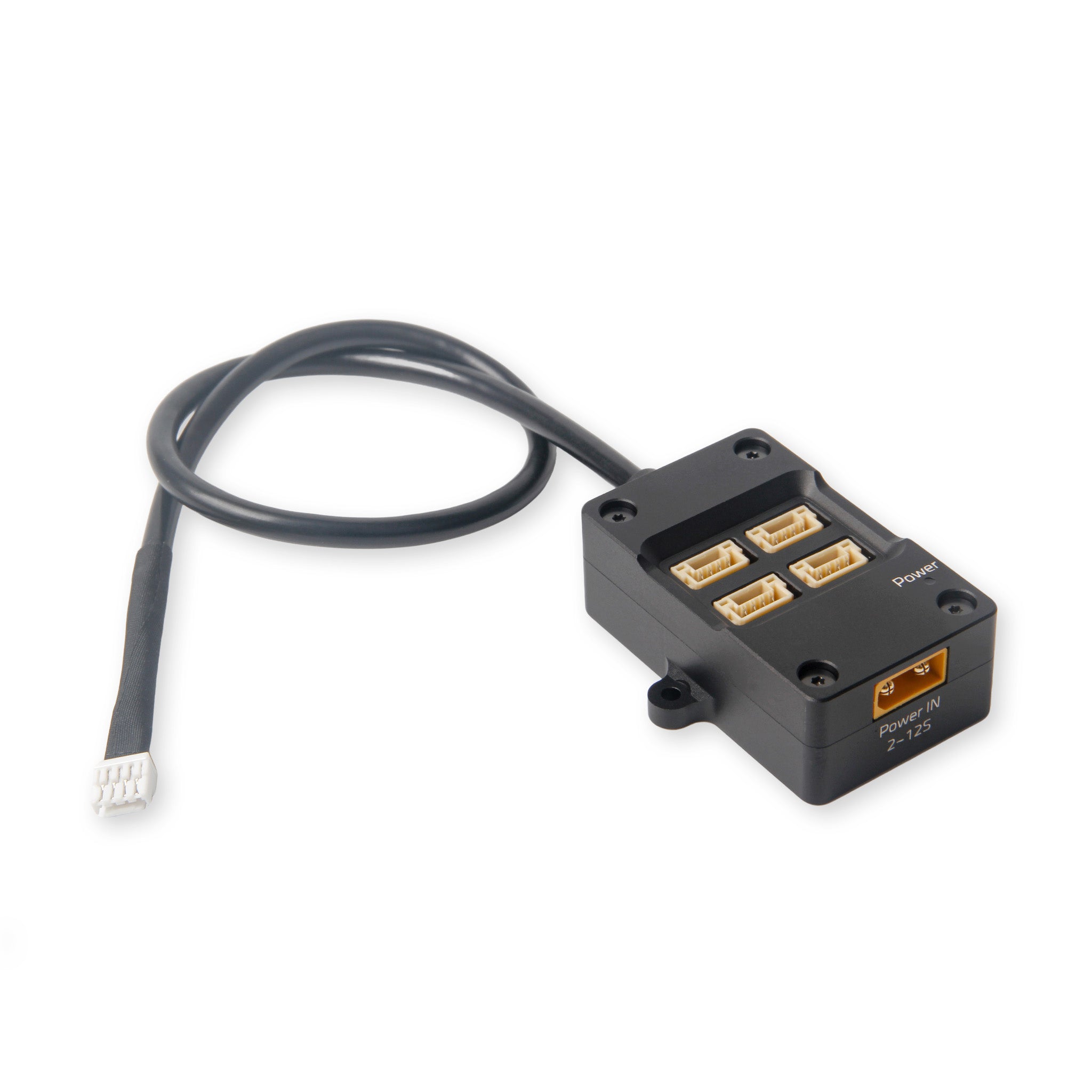
Yellow XT30 Power IN 2–12S — without it, F9P + H-Flow only draw FC 5V
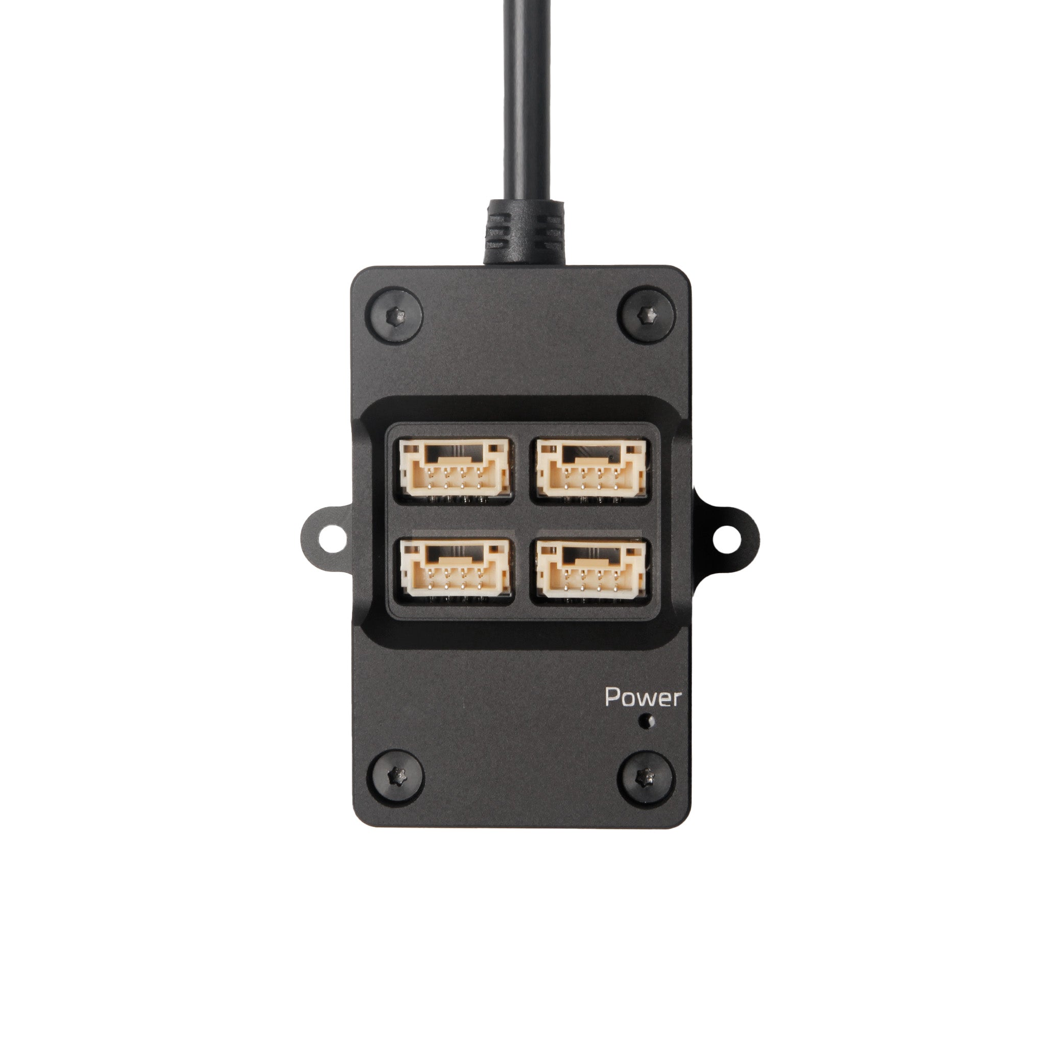
1× CAN from the FC → multiple DroneCAN devices
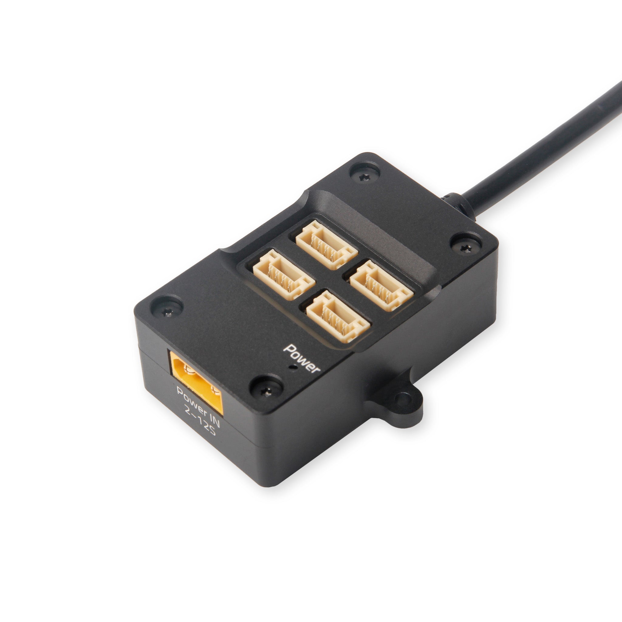
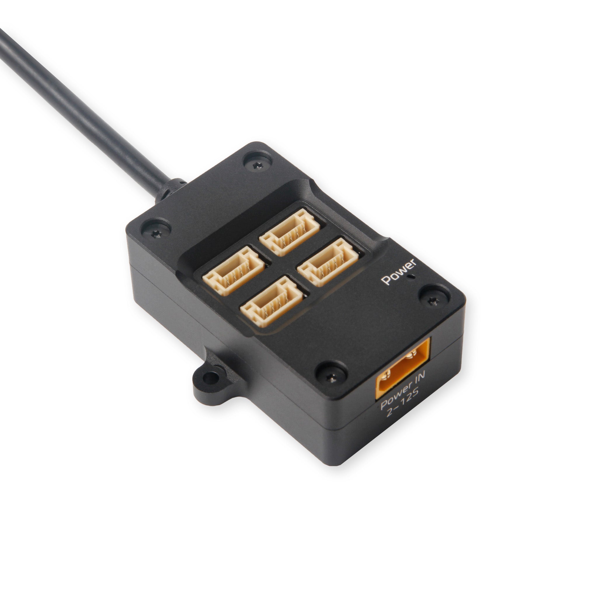
The Mini has one CAN connector. We want F9P Helical and H-Flow on it. So we use the CAN Hub 27 cm: splitter plus its own power from the pack.
Why this hub
Without a hub you DIY Y-splits and termination. Holybro’s hub does that cleanly. Order: $27.59 · Store: holybro.com — CAN Hub.
The hub is powered: pack → XT30 → internal step-down → 5.2 V on the CAN ports (up to 1 A per port, max 3 A total). Holybro warns that FC CAN 5V often sags when several peripherals share the same rail (Pixhawk: other ports together ≈ 1.5 A).
| Device on the hub | ≈ 5 V current | Note |
|---|---|---|
| F9P Helical | ~250 mA | Holybro spec |
| H-Flow (flow + ToF) | extra 100 mA+ | ToF/laser + MCU |
| Total | quickly >400 mA | too thin beside M9N/ELRS on the same FC 5V pool |
Do this: XT30 from 6S (via XT30↔XT60 adapter or a Y tap) into the hub. The CAN cable to Pixhawk CAN1 is for data. Details: power & capacitors.
LD-06 is not a CAN device — it sits on TELEM1.
What we do
- Hub on CAN1 of the Pixhawk 6X Mini.
- F9P + H-Flow on the hub ports.
- Connect XT30 Power-In from the pack.
- 120 Ω termination between CANH–CANL at the bus ends (Holybro: sometimes a software toggle — holybro-can-termination-toggle.md).
- Strain-relieve the cables — vibration tug on JST-GH is a classic intermittent CAN fault.
DroneCAN on ArduPilot (FC side)
Generic procedure: IQ Motion — DroneCAN + ArduPilot/PX4. That guide targets Vertiq DroneCAN ESCs. We do not run motors over CAN (ESC = Pacer PWM/DShot). Still applicable: bus hardware, bitrate, node IDs, ArduPilot CAN params, Mission Planner node check.
Official: DroneCAN Setup advanced · CAN Bus Setup.
Bus rules
| Rule | Why |
|---|---|
| Unique node ID per device | Duplicate IDs → unpredictable bus |
| Same bitrate on FC + every node | Mismatch → missing nodes |
| Avoid colliding with the FC | ArduPilot typically uses node ID 10 (CAN_D1_UC_NODE) |
| DNA | Node ID 0 = dynamic allocation |
Parameters (CAN1)
- Set a frame type in Mission Planner (Setup).
CAN_P1_DRIVER = 1→ write + reboot.CAN_P1_BITRATE— Holybro stack usually 1000000 (Vertiq’s 500000 default does not apply to our sensors).- Reboot, then set
CAN_D1_PROTOCOL = 1(DroneCAN) andCAN_D1_UC_NODE(FC node ID; default 10 is fine if free). - Write + reboot.
Not needed for this build: CAN_D1_UC_ESC_BM / ESC indices — those are for DroneCAN ESCs.
Then configure sensors: F9P · H-Flow.
See nodes (Mission Planner)
- Setup → Optional Hardware → DroneCAN/UAVCAN
- Choose MAVLinkCAN1
- Nodes should appear (F9P, H-Flow, …)
- Per node: Menu → Parameters
Missing a node? Check power, termination, bitrate, duplicate node ID. Also DroneCAN GUI Tool / SLCAN.
What ArduPilot detects on our bus
| Peripheral | How to enable | Our device |
|---|---|---|
| GPS | GPS1_TYPE = 9 (DroneCAN) |
F9P Helical |
| Compass | Auto via DroneCAN | F9P IST8310 |
| Rangefinder | RNGFND1_TYPE = 24 + RNGFND1_ADDR matches node |
H-Flow ToF |
| Optical flow | FLOW_TYPE = 6 |
H-Flow |
GPS/compass/baro are auto-identified; rangefinder must be set to type 24 explicitly.
Extra params (light bus)
| Parameter | Tip |
|---|---|
CAN_D1_UC_POOL |
Default can often be lowered with light traffic (GPS + flow) |
CAN_D1_UC_NODE |
Autopilot node ID (default 10) — keep unique |
CAN_D1_UC_OPTION bit 0 |
Clear DNA database on next boot |
CAN_D1_UC_OPTION bit 1 |
Ignore DNA node conflicts |
CAN_D1_UC_OPTION bit 3 |
Ignore DNA node unhealthy |
Intentionally not for us (now)
CAN_D1_UC_ESC_BM/CAN_D1_UC_SRV_BM/CAN_D1_UC_ESC_OF- DroneCAN LED, power-module monitor type 8, CAN-FD
CAN_D1_PROTOCOL2mixed protocols
SLCAN / GUI (Pixhawk 6X = H7)
- Pixhawk 6X Mini is H7 → SLCAN Access on F7/H7; prefer MAVLink SLCAN.
- COM-port SLCAN is disabled when armed — configure peripherals disarmed.
- Tools: Mission Planner DroneCAN panel or DroneCAN GUI.
DNA database: ArduPilot stores node-ID ↔ hardware-ID. Swapping a node (same ID, different HW) causes a conflict → CAN_D1_UC_OPTION bit 0 or bit 1.
Local refs: holybro-about-dronecan.md · holybro-can-termination-toggle.md.
Read next
- F9P Helical — RTK on this bus
- H-Flow — optical flow + ToF
- Power & capacitors — XT30 Power-In
- Pixhawk 6X Mini — CAN1 mapping
ArduPilot wiki
Choice log
| What | Holybro CAN Hub 27 cm (powered, XT30) |
| Why | F9P + H-Flow on one Mini CAN1 without hand-soldering |
| Our pick | Hub 27 cm — XT30 Power-In required; no DIY Y until we need custom lengths |
Product Info
CAN Hub
- Handle:
can-hub - Vendor: PCBA & Aluminum
- Product type: GPS Accessories
- Store URL: https://holybro.com/products/can-hub
Description
The Holybro CAN Hub is a powered CAN port expansion module developed for various flight controllers and their supporting peripherals. This CAN Hub is integrated with a step-down power supply. It supports 2-12S power input and 5V CAN power output, and can expand one CAN port into up to four ports while providing stable 5V/1A power for each port with its dedicated power input. Most flight controllers have a 5v output on the CAN port, but the voltage can sometimes be lower than 5v because it is affected by other devices that is connected to the FC, and there is a ~3A current limit for the sum of all ports (Excluding Telem1). The power supply of this hub is independent and can guarantee a stable 5V power source to your CAN peripherals. Technical Specification: Input voltage: 2S – 12S Output voltage: 5.2V±0.15V Max current output: 1.0A @ 5.2V per CAN port. The total current of the 4 ports cannot exceed 3A. Power-In Connector: XT30 CAN in Connector: GHR-4V-S CAN Out Connector: 4 Port BM04B-GHS-TBT Downloads: 3D CAD File
Variants
- 27cm: $27.59 — SKU
18085— available=None - 42cm: $27.59 — SKU
18086— available=None
Options
- Cable Length: 27cm, 42cm
Photos