
Pixhawk 6X Mini
Besteld: Pixhawk 6X × 1 — Mini baseboard / PM02D
Store: https://holybro.com/products/pixhawk-6x (variant Mini / PM02D)
Docs: https://docs.holybro.com/autopilot/pixhawk-6x/overview
Mini ports: https://docs.holybro.com/autopilot/pixhawk-baseboards/pixhawk-mini-baseboard-ports
Standard v2 ports: https://docs.holybro.com/autopilot/pixhawk-baseboards/pixhawk-baseboard-v2-ports
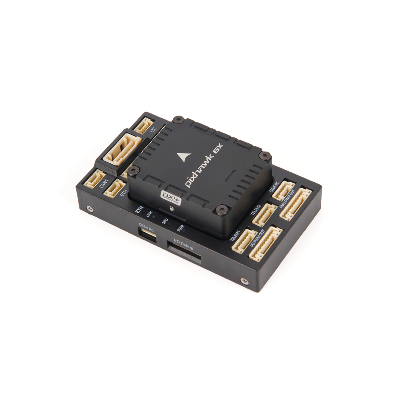
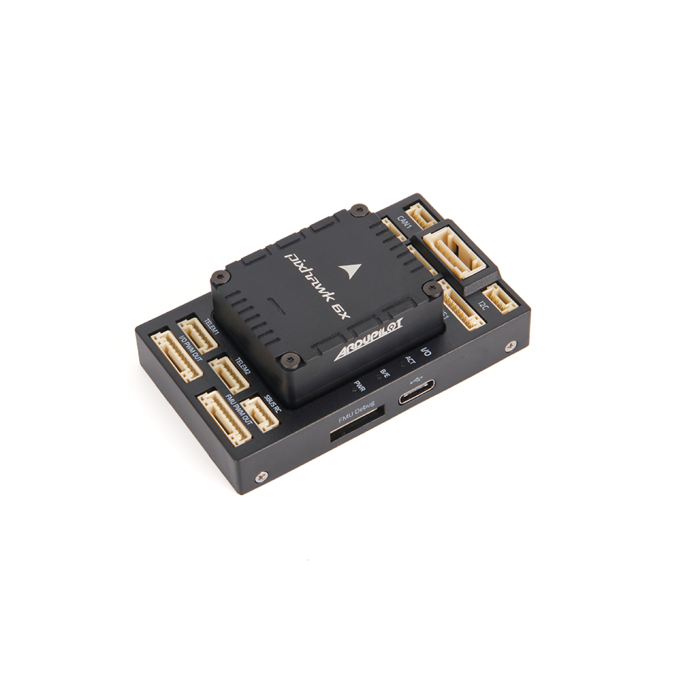
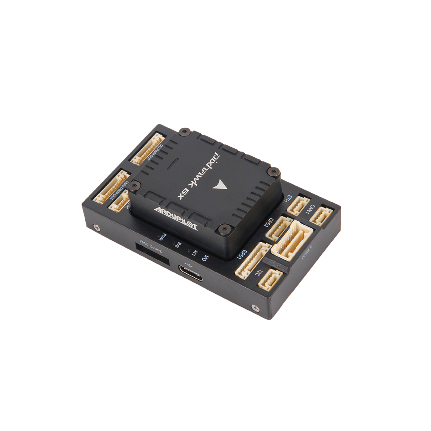
FMUv6X flight controller with the Mini baseboard. Same autopilot module as the full Pixhawk 6X; smaller I/O board for compact airframes such as the AOS UL8 V5. Runs PX4 and ArduPilot (Pixhawk6X).
Pixhawk 6X vs Pixhawk 6X Mini
Holybro sells one Pixhawk 6X flight-controller module (SKU 11073). You choose the baseboard that plugs onto it:
| Pixhawk 6X (Standard) | Pixhawk 6X Mini (this build) | |
|---|---|---|
| FC module | Same FMUv6X (STM32H753, triple IMU, dual baro, Ethernet PHY) | Same |
| Baseboard | Standard v2A / v2B (aluminum) | Mini |
| Baseboard size | ~52.4 × 102 × 16.7 mm | ~43.4 × 72.8 × 14.2 mm |
| Baseboard weight | ~51–72 g (source-dependent) | ~26.5 g |
| Typical use | Larger drones, many peripherals | Compact long-range / FPV-style frames |
| Ports | Full Standard set | Reduced — see matrix below |
| Mount | Larger footprint | 30.5 mm stack-friendly, fits AOS UL8 V5 |
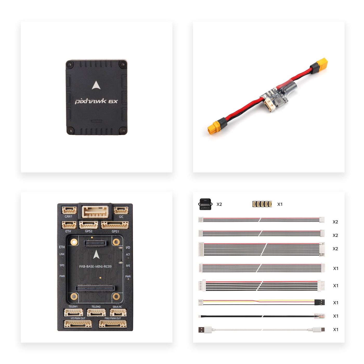
| Kit we bought | — | Mini + PM02D digital power module |
In short: the “brain” is identical; Mini is the compact baseboard. Full port matrix: ports-vergelijking.md.
Processors & sensors — what they do
This is the FMUv6X module (same silicon on Standard and Mini). Specs below match Holybro’s current Rev8 shipping; older boards may be Rev3/4. (These are Pixhawk 6X specs, not 6C — 6C is the cheaper line with less IMU redundancy.)
The two processors
| Chip | Role | What ArduPilot uses it for |
|---|---|---|
| FMU — STM32H753 (Cortex-M7 @ 480 MHz, 2 MB flash, 1 MB RAM) | Main computer | Runs ArduCopter (Pixhawk6X): EKF, navigation, missions, serial/CAN drivers, logging. Extra CPU/RAM headroom for OA, heavy logging, and many peripherals. |
| IO — STM32F103 (Cortex-M3 @ 72 MHz, 64 KB SRAM) | I/O coprocessor (IOMCU) | Drives MAIN OUT PWM to the ESCs. If the FMU hangs, the IOMCU can still output failsafe PWM — classic Pixhawk split of “brain” vs “muscles”. |
Short version: the H753 thinks; the F103 keeps commanding motors if things go wrong.
On-board sensors (Rev8 — current shipping)
| Sensor | Chip(s) | Purpose | In ArduPilot |
|---|---|---|---|
| Accel / Gyro (IMU) ×3 | 3× ICM-45686 (BalancedGyro™) | Acceleration + angular rate → attitude and rates | Core of EKF3 / attitude control. Three IMUs on separate buses with isolated power: ArduPilot can fail over (EK3_IMU_MASK / health checks). Vibration isolation + IMU heater reduce motor noise and temperature drift. |
| Barometer ×2 | ICP20100 + BMP388/580/581 | Air pressure → relative altitude | BARO in the EKF for altitude / climb rate (alongside GPS). Dual baro = redundancy. |
| Magnetometer | BMM150 | Earth’s magnetic field → heading | Internal compass (COMPASS). On a quad with power leads it is often noisy — we also use the compass on Micro M9N / F9P and calibrate carefully. |
Previous revisions (Rev3/4)
| Sensor | Chip(s) |
|---|---|
| Accel/Gyro | BMI088 or ICM-20649 · ICM-42688-P · ICM-42670-P (three IMUs, different mix) |
| Barometer | 2× BMP388 |
| Mag | BMM150 |
ArduPilot loads the right drivers per board; you do not configure chip names by hand. In Mission Planner / logs you can see which IMU/baro instances are healthy. Firmware target stays Pixhawk6X.
How this ties to ArduPilot
- ArduPilot is the software on the FMU (H753) — not on the sensor chips themselves.
- IMUs + baro + mag feed EKF3: estimate of attitude, velocity, position. Without a solid IMU, no flight mode stays stable; GPS / optical flow (H-Flow) refine position.
- Redundancy (3× IMU, 2× baro) is why we picked 6X over 6C: ArduPilot can drop a bad sensor and keep flying.
- External sensors (GPS, LiDAR, ELRS) use UARTs/CAN on the Mini baseboard — alongside this on-board set; see ports & wiring and step 2.
- Always flash the matching build: Mission Planner → Pixhawk6X (firmware · ArduPilot + ELRS).
Holybro: Pixhawk 6X overview · ArduPilot: Pixhawk 6X.
I/O & ports — what they are (and what we use)
Holybro’s feature list mostly describes the Standard baseboard. The Mini omits some connectors; the FC module is the same. Below: what each port does, and how we wire this build. Map overview: ports & wiring.
PWM outputs (motors / servos)
| Holybro spec | Meaning | Our build |
|---|---|---|
| 16× PWM servo outputs | 8× MAIN OUT (IOMCU) + 8× AUX OUT (FMU) to ESCs or servos. | MAIN OUT → Pacer 60A V2 → 4× F100 (+ LR8 props). AUX kept spare (gimbal/servo later). |
| 3.3 V / 5 V signal mode (hardware-switchable) | PWM logic level. Switching needs a baseboard modification. | We keep the stock level — no mod. Pacer accepts normal FC PWM/DShot. |
Classic RC inputs
| Spec | Meaning | Our build |
|---|---|---|
| DSM / Spektrum | Dedicated Spektrum satellite connector. | Unused. |
| PPM / S.Bus input | Classic receiver; on Mini as SBUS RC (Standard: separate RC IN). | Unused. RC is ELRS CRSF on a UART. |
| Analog/PWM RSSI + S.Bus out | RSSI in + SBUS pass-through. | Unused (partly on Mini’s SBUS RC). |
Why not SBUS? ExpressLRS + XR4 speaks CRSF on a full UART (setup) — lower latency and telemetry back to the TX16S. Leave SBUS/DSM empty.
Serial ports (UARTs)
Holybro’s “4 general purpose serial ports” ≈ TELEM1–3 + UART4 on Standard. Mini has TELEM1 + TELEM2 only (no TELEM3, no UART4&I2C combo). GPS1/GPS2 are serial too, but dedicated connectors.
| Port | Role | Flow-control / notes | Our build (ArduPilot) |
|---|---|---|---|
| TELEM1 | General UART | Full flow-control; separate 1.5 A 5 V limit | LD-06 LiDAR — SERIAL1, PROTOCOL=11, baud 230400. Good fit: LiDAR wants stable 5 V + a fixed UART. |
| TELEM2 | General UART | Full flow-control | XR4 ELRS — SERIAL2, PROTOCOL=23 (CRSF). |
| TELEM3 | Extra UART | Full flow-control | Not on Mini — mapping stays tight. |
| UART4 + I2C + GPIO | Serial + I2C + NFC reader line | Combo connector on Standard | Not on Mini — NFC irrelevant here. |
| GPS1 | “Full” GPS port | UART + I2C (compass) + safety switch / buzzer pins | Micro M9N — SERIAL3: GPS + external compass + safety. |
| GPS2 | “Basic” GPS port | Fewer pins (no full safety set) | Spare — second GPS or later sensor; not the LD-06 (that’s on TELEM1). |
Serial = talk line between ArduPilot and a device. Pick protocol per SERIALn_PROTOCOL. Do not share a UART between devices.
I2C
| Spec | Meaning | Our build |
|---|---|---|
| 1× I2C port (4-pin) | Bus for slow sensors (external baro, compass, airspeed, …) | Spare. Compass already on GPS1/M9N and partly on-board; PM02D uses digital POWER1 (its own PM I2C, not this jack). |
Ethernet
| Spec | Meaning | Our build |
|---|---|---|
| 100 Mbps Ethernet (transformerless, AN2190 50 Ω) | Fast link to a companion computer for offboard/MAVLink | Spare — see later. Not needed for maiden; present on Mini. |
SPI
| Spec | Meaning | Our build |
|---|---|---|
| 1× SPI bus (2× CS, 2× DRDY, SYNC, RESET) | External high-speed sensors / SPI payloads | No connector on Mini. On-board IMUs use internal SPI; we add no external SPI device. |
CAN
| Spec | Meaning | Our build |
|---|---|---|
| 2× CAN (silent / ESC RX-MUX control) | DroneCAN/UAVCAN for GPS, flow, ESCs, … | CAN1 → CAN Hub → F9P Helical + H-Flow. CAN2 not on Mini — one bus via the hub is enough. |
Power & AD/IO
| Spec | Meaning | Our build |
|---|---|---|
| 2× Power input (SMBus) | Digital power modules: FC power + voltage/current over SMBus/I2C | POWER1 only → PM02D. POWER2 not on Mini. |
| AD & IO | Extra analogs, PWM/capture, debug/GPIO (e.g. nARMED) | Not on Mini. No analog airspeed/RSSI via this connector. |
| Debug (FMU / IO) | SWD + console for developers | Firmware debug only; day-to-day flash via module USB-C. |
Summary: our locked mapping
POWER1 ──► PM02D ◄── battery           (digital PM / SMBus)
TELEM1 ──► LD-06                       (LiDAR / proximity)
TELEM2 ──► XR4 ◄── TX16S               (ELRS CRSF, not SBUS)
GPS1   ──► Micro M9N                   (GPS + compass + safety)
CAN1   ──► Hub ──► F9P + H-Flow        (RTK + optical flow)
MAIN   ──► Pacer ──► 4× F100           (PWM/DShot)
GPS2 / I2C / ETH / AUX OUT / SBUS/DSM ──► spare or unused on purpose
Details + build order: ports & wiring · step 2 — FC & power. Mini vs Standard matrix: table below and ports-vergelijking.md (repo).
Port reservation (locked)
Fixed assignment for this build. Change only via docs update.
| Port | ArduPilot | Device | Docs | |
|---|---|---|---|---|
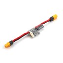 |
POWER1 | digital PM | PM02D | power + I2C telem |
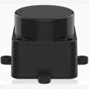 |
TELEM1 | SERIAL1 | LD-06 | PROTOCOL=11, baud 230400 |
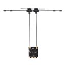 |
TELEM2 | SERIAL2 | XR4 ELRS | CRSF PROTOCOL=23 · setup |
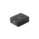 |
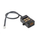
GPS1 | SERIAL3 | Micro M9N | GPS + compass + safety |
 |
GPS2 | SERIAL4 | spare | — |
 |
CAN1 | DroneCAN | CAN Hub → F9P + H-Flow | mount: 07 |
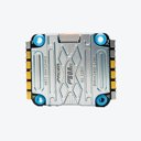 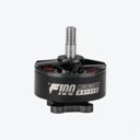  |
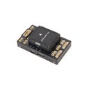
MAIN OUT | PWM / DShot | Pacer 60A V2 → F100 ×4 | props: LR8×4.2×3 |
 |
USB-C (module) | SERIAL0 | GCS / flash | Mission Planner |
|
I2C / ETH / AUX | — | spare | — |
|
SBUS RC / DSM | — | unused | RC via XR4 on TELEM2 |
Frame: AOS UL8 V5 · TX: TX16S MK3 MAX · cables: Mini cable set.
Not on Mini: POWER2 · TELEM3 · CAN2 · UART4&I2C · SPI · AD&IO · USB JST-GH.
Ports — Standard vs Mini
| Connector | Standard v2 | Mini | Reservation |
|---|---|---|---|
| POWER1 | ✅ | ✅ | PM02D |
| POWER2 | ✅ | ❌ | — |
| TELEM1 | ✅ | ✅ | LD-06 |
| TELEM2 | ✅ | ✅ | XR4 |
| TELEM3 | ✅ | ❌ | — |
| GPS1 | ✅ | ✅ | Micro M9N |
| GPS2 | ✅ | ✅ | spare |
| CAN1 | ✅ | ✅ | Hub + F9P + H-Flow |
| CAN2 | ✅ | ❌ | — |
| UART4 & I2C | ✅ | ❌ | — |
| I2C (4-pin) | ✅ | ✅ | spare |
| SPI | ✅ | ❌ | — |
| ETH | ✅ | ✅ | spare |
| USB JST-GH | ✅ | ❌ | USB-C on module |
| AD&IO | ✅ | ❌ | — |
| AUX & RSSI (separate) | ✅ | ❌ | — |
| RC IN / SBUS RC | ✅ RC IN | ✅ SBUS RC | unused (ELRS) |
| DSM RC | ✅ | ✅ | unused |
| MAIN OUT (8×) | ✅ | ✅ | Pacer / F100 |
| AUX OUT (8×) | ✅ | ✅ | spare |
| FMU / IO Debug | ✅ | ✅ | development |
Present on Mini
POWER1 · TELEM1 · TELEM2 · GPS1 · GPS2 · CAN1 · I2C · ETH · DSM RC · SBUS RC · MAIN OUT · AUX OUT · debug ports · USB-C on the FC module.
Missing on Mini (vs Standard)
POWER2 · TELEM3 · CAN2 · UART4&I2C combo · SPI · AD&IO · USB JST-GH · separate AUX&RSSI block.
Notes for this build
- Digital power module (PM02D) on POWER1 only — no POWER2 backup path.
- ELRS on TELEM2 / SERIAL2 (CRSF), not SBUS/RC IN.
- LD-06 on TELEM1 / SERIAL1 (Lidar360).
- Pinouts:
holybro-mini-baseboard-ports.md, Standard snapshotholybro-baseboard-v2-ports.md. - Stack mount: 30.5×30.5 mm on the AOS UL8 V5.
Sources
- Store: holybro.com — Pixhawk 6X
- Overview: docs.holybro.com — Pixhawk 6X
- Mini ports: docs.holybro.com
- Standard v2 ports: docs.holybro.com
- Local comparison: ports-vergelijking.md
ArduPilot wiki (implementation)
Official wiki pages for configuring / testing this part in ArduPilot:
- Pixhawk 6X — board & ports
- Loading firmware onto Pixhawk
- Mounting the flight controller
- Accelerometer calibration
- Configuring hardware (overview)
- Initial setup
Decision report
What it is
Holybro Pixhawk 6X flight-controller module (FMUv6X: STM32H753, triple IMU, dual baro) op een Mini-baseboard. Dezelfde “computer” als Standard 6X; kleinere I/O-board.
What it’s for
Autopilot voor ArduPilot Copter: stabilisatie, missies, RTK/GPS, DroneCAN-sensoren, ELRS-RC. Kern van de UL8-build.
Our choice
Pixhawk 6X Mini + PM02D — licht (~26 g baseboard), 30.5 mm stack, genoeg poorten voor GPS1, CAN1, TELEM1/2, MAIN OUT. Gekozen boven Standard vanwege gewicht/formaat op AOS UL8.
Alternatives (approx. prices)
| Alternative | ≈ prijs | When |
|---|---|---|
| Pixhawk 6X Standard v2 | ≈ €290–340 (kit) | Meer UARTs, POWER2, SPI, AD&IO |
| Pixhawk 6C / 6C Mini | ≈ €180–280 | Goedkoper, minder IMU-redundantie dan 6X |
| CubePilot Cube Orange+ | ≈ €450–800 | Premium industrieel / carrier-ecosysteem |
| Matek / SpeedyBee H743 “solder FC” | ≈ €50–120 | Lichter/goedkoper FPV; minder Pixhawk-standaard & redundantie |
Online tests & reviews
- Pixhawk 6 vs 6C vs 6X vs Mini (2026) — heldere productlijn-vergelijking.
- JOUAV FC guide — Pixhawk 6X vs Cube — professionele keuzematrix.
- ArduPilot Discourse: Pixhawk vs solder FC — community over IMU-heater, IOMCU, weight.
- Docs: Holybro Pixhawk 6X · ArduPilot Pixhawk6X
Product Info
Pixhawk 6X
- Handle:
pixhawk-6x - Vendor: PCBA
- Product type: Flight Controller
- Store URL: https://holybro.com/products/pixhawk-6x
Description
Key Design Points Redundancy: 3x ICM-45686 IMU sensors ( ±32g) with BalancedGyro™ technology & 2x Barometer sensors High-performance STM32H753 Processor with a clock speed of up to 480 MHz Modular flight controller: separated IMU, FMU, and Base system connected by a 100-pin & a 50-pin Pixhawk® Bus connector. Triple redundancy domains: Completely isolated sensor domains with separate buses and separate power control All-New advanced durable vibration isolation material with resonance frequency in the higher spectrum Ethernet interface for high-speed mission computer integration. Transformerless can be achieved using 50 Ohm termination resistors at the target device ( AN2190 50 Ohm termination ). Temperature-controlled IMU board, allowing the optimum working temperature of IMUs Hardware switchable 3.3V or 5V signal mode (requires baseboard modification) Digital power module support for better voltage and current data accuracy All new Vibration Isolation Design This new vibration isolation design uses the same c ustom-formulated durable isolation material as the Pixhawk 6X Pro , instead of the traditional foam design . B acked by extensive R&D and testing , it offers optimal IMU damping characteristics with a resonance frequency in the higher spectrum, perfect for industrial and commercial drones. Note: The Rev 8 Version is supported in the PX4 1.14.3 release or later, as well as the Ardupilot 4.5.0 stable release or later. It ships with PX4 firmware by default. The user can also use the Ardupilot firmware by flashing the firmware via Mission Planner or QGroundControl. Power module comparison chart Specification Processors & Sensors FMU Processor: STM32H753 32 Bit Arm® Cortex®-M7, 480MHz, 2MB flash memory, 1MB RAM IO Processor: STM32F103 32 Bit Arm® Cortex®-M3, 72MHz, 64KB SRAM On-board sensors (Shipping Currently, Rev8) Accel/Gyro: 3x ICM-45686 (with BalancedGyro™ Technology) Barometer: ICP20100 & BMP388/580/581 Mag: BMM150 NXP EdgeLock SE050 Plug & Trust hardware secure element Electrical data Voltage Ratings: Max input voltage: 6V USB Power Input: 4.75~5.25V Servo Rail Input: 0~36V Current Ratings: Telem1 & GPS2 combined current limit: 1.5A All other ports combined current limit: 1.5A PWM Signal Voltage: Default 3.3V (Adjustable to 5V with a change onboard resistor) Operating Temperature: -25-85°C Mechanical data Dimensions Flight Controller Module: 38.8 x 31.8 x 16.8mm Standard Baseboard: 52.4 x 102 x 16.7mm ( Aluminum ) Mini Baseboard: 43.4 x 72.8 x 14.2 mm Weight Flight Controller Module: 31.3g Standard Baseboard: 72.5g ( Aluminum) Mini Baseboard: 26.5g Reference Links Full Specification Pixhawk Baseboards Ports Power Module Setup Guide Dimensions Downloads Sample Wiring Diagram Latest info on Supported Firmware. For other technical information, please visit https://docs.holybro.com/. SKU 11073 includes: Pixhawk 6X Flight Controller Module Controller + Baseboard + Power Module Set includes: Pixhawk 6X Flight Controller Module Standard Baseboard v2A/v2B or Mini Baseboard PM02D HV Power Module Cable Set Accessories: Pixhawk PWM Cable for Tekko32 4in1 ESC Standard Baseboard Mounting Plate
Variants
- Standard v2A / PM02D: $320.98 — SKU
11073+18117+15011— available=None - Standard v2B / PM02D: $320.98 — SKU
11073+18125+15011— available=None - Mini / PM02D: $286.98 — SKU
11073+18074+15011— available=None - None (FC Module Only) / FC Module Only: $166.99 — SKU
11073— available=None
Options
- Pixhawk Baseboard Version: Standard v2A, Standard v2B, Mini, None (FC Module Only)
- Power Module: PM02D, FC Module Only
Photos