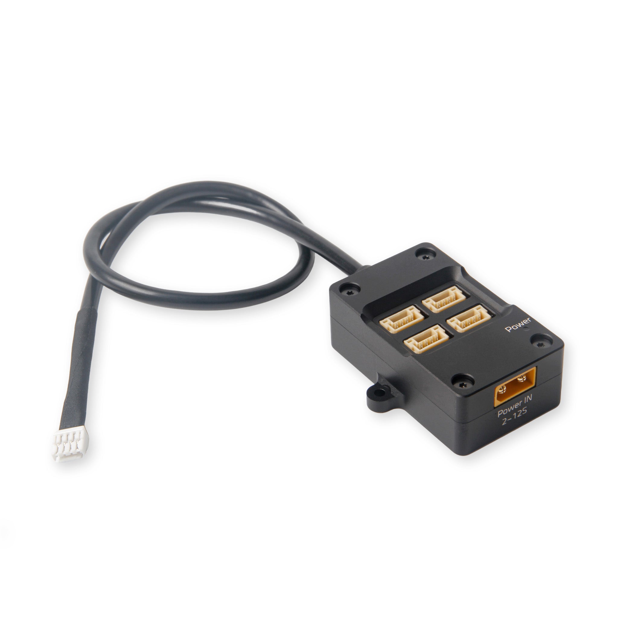

Ports & wiring on the Pixhawk 6X Mini
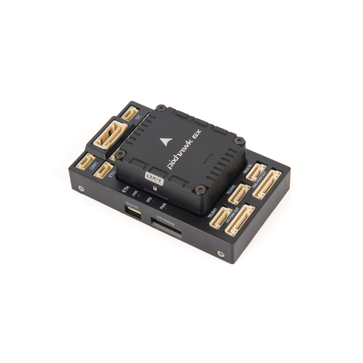
Pixhawk 6X Mini
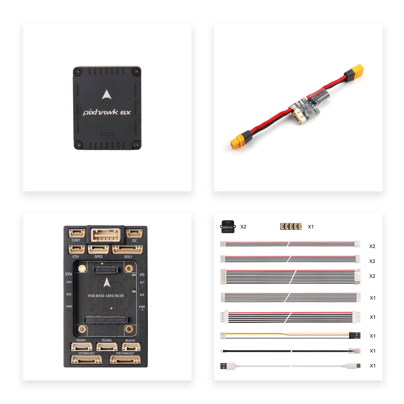
Mini-baseboard / poorten
On the Mini, serial ports are scarce. We lock the mapping before soldering — otherwise ELRS and LiDAR fight for the same UART.
Per Holybro I/O feature (PWM, TELEM, GPS, CAN, ETH, …) plus what we use or leave empty: Pixhawk 6X Mini — I/O & ports.
Locked mapping (ArduPilot)
| Function | Port | Protocol / type |
|---|---|---|
| Battery / FC power | POWER1 via PM02D | digital (I2C) |
| UART-GPS + compass | GPS2 | Micro M9N (GPS2_TYPE=1) |
| GPS1-stekker | GPS1 | leeg — F9P is DroneCAN (GPS1_TYPE=9) |
| CAN | CAN1 + CAN Hub | F9P Helical + H-Flow |
| ELRS (CRSF) | TELEM2 / SERIAL2 | XR4 ← TX16S |
| LiDAR proximity | TELEM1 / SERIAL1 | LD-06 (PRX1_TYPE=16) |
| Motors | MAIN OUT → Pacer | DShot/PWM |
Do not share: TELEM1 stays with LD-06; TELEM2 with ELRS. No TELEM3 on the Mini.
Full Peripheral Hardware map (wiki → our stack): project intro · source Optional Hardware.
Cabling (from ArduPilot cabling guide)
Practical for this build (Cable Design Guidelines):
- Colour: red = +, black = GND; prefer twisted pairs for data.
- CAN: CAN_H / CAN_L twisted; 120 Ω termination at bus ends (CAN Hub).
- GPS / compass: keep away from ESC, motor leads, video TX.
- Power vs signal: keep battery runs short; avoid long parallel runs of signal beside power (EMI).
- Strain-relieve JST-GH connectors.
More detail: ArduPilot + ELRS and Step 4 — Radio.
Power in parallel, signals separate
Power: see Power & capacitors. Signals: short, twisted runs where possible; GPS/compass away from ESC and video.
Build order (short)
- Frame + propulsion
- FC & power
- GPS/RTK/flow
- Radio
- Flow check + LiDAR
- Config & maiden
Related
ArduPilot wiki (implementation)
Official wiki pages for configuring / testing this part in ArduPilot:
- Pixhawk 6X (UART mapping)
- Serial port options
- Flight controller wiring
- Telemetry port setup
- CRSF / ELRS
- Cable design guidelines
- Peripheral / Optional Hardware (index)
Photos